Surface paths: Swarf Machining
Introduction
This topic will explain the options found in the Surface paths tab of the Swarf Machining operation.
Surface paths
The Surface paths tab allows you to define the surfaces to be machined, dictate how they are cut, define the clearance, start point, surface quality, and extensions.
| ... |
Machining direction dialog - selecting the ellipses button brings opens the Machining direction dialog. |
- Top - Machines the part from (0,0,1) Z direction.
-
Other direction - Machines the part from user defined direction (1,0,0)
Geometry Selection
This section provides all of the potential geometry selections for Swarf milling. The available options change slightly depending on the Advanced Control Strategy that is selected.
Note: For all of the following geometry selections,
you select the check box next to the name of the geometry item to include
the item in the toolpath calculation. If the check box is not selected,
then the geometry item is not used to compute the toolpath. After selecting the check box of the geometry
item, click ![]() to enable
selection mode and select the appropriate geometry from the graphics area.
If you turn on a geometry item but do not select geometry, an error message
displays when you compute the toolpath.
to enable
selection mode and select the appropriate geometry from the graphics area.
If you turn on a geometry item but do not select geometry, an error message
displays when you compute the toolpath.
-
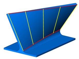
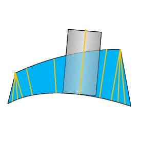
Swarf surfaces - are the target surfaces for the feature. This is the geometry that you want the entire flute length of the tool to cut along. Only the Automatic strategy requires Swarf surfaces selection, but they can be selected for any strategy. These surfaces are used when applying a Swarf Offset (stock to leave) unless the Upper Curve and Lower Curve are selected. In this case the curves are used to create the offset.
-
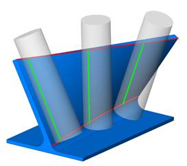
Floor surfaces - are generally below the swarf surfaces and can be selected when you need to avoid cutting the floor or when you want to apply an allowance (Floor clearance) to the floor surfaces. When you turn on Floor Surfaces, the system tries to project (drop) the tool past the swarf surface down to the floor.
-
Tilt lines - can be selected to define the orientation of the tool along the cut. Tilt lines are only used with the Sync with Tilt Lines strategy.
-
Guide Curves
You can select the Guide Curves check box to turn on the ability to select guide curve geometry.
-
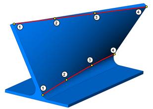
Upper - is the upper edge curve of the feature which is used to define the upper point for the tool orientation and is used when applying a Swarf Offset. Generally, this is the upper edge of the Swarf surfaces.
-
Lower - is the lower edge curve of the feature which is used to define the lower point for the tool orientation and is used when applying a Swarf Offset. Generally, this should be the lower edge of the Swarf surfaces. The chain direction (Start Point) of the lower curve can be used to set the cutting direction and cutting side of the feature.
-
Swap
The swap check box is used to exchange the upper and lower curves for the toolpath calculation. The upper curve is applied as the lower curve and the lower curve is applied as the upper curve. This can be helpful when using the Automatic Strategy and selecting only Swarf Surfaces. This is provided in the event the software detects the curves incorrectly.
-
Swarf Clearance - is used to set an allowance to define how close to cut to the swarf surfaces. You don't have to select Swarf surfaces in order to apply an offset. The offset is applied using the Upper Curve and Lower Curve geometry.
-
Floor clearance - is used to apply an allowance to define how close to cut to the floor surfaces. You must select Floor Surfaces to apply a floor clearance. Negative values are not supported.
Proper Geometry Selections
When using the Automatic strategy, you must select a Swarf Surface. The Swarf Surfaces are not required for any other strategy, but can still be selected. When using any strategy other than Automatic, you can choose to select either Swarf Surfaces or the Upper and Lower Curve. All other selections are explained next.
-
For Sync with Tilt Lines, you must also select tilt line geometry to define the tool orientation along the feature.
-
If you use Sync with Main Direction and select Line, then you must select a line to define the direction. (This is not the same as the tilt line geometry and is only selected in the wizard.)
-
The Floor surfaces are optional for all strategies, and should be used when needed based on the feature.
Tip: The software attempts to automatically detect the upper and lower curves from the selected swarf surfaces. Selecting the Upper Curve and Lower Curve may help improve or speed up the toolpath calculation for complicated or open part geometries.
Machining
-
Side - Select one of the following options to control which side of the part is cut. These options are used together with the Direction parameter.
-
Left - cuts on the left side of the part for open features.
-
Right - cuts on the right side of the part for open features.
-
Inside - cuts the inside of a closed contour.
-
Outside - cuts the outside of a closed contour.
-
Auto-detect - select this option to allow the system to attempt to set the proper machining side of the part using the geometry selections. This works best when the whole part is selected, the swarf surfaces form a closed boundary, or the top and bottom surfaces are aligned horizontally.
-
Surface Normals - uses the surface normal of the feature geometry to define the cutting side.
The following options are only used with the One Way cutting method. (The feature uses one-way cutting unless the Depth Steps (on the Multi Cuts tab) are set to greater than one and then Zig Zag is selected. The following options are no longer available when using Zig Zag.)
-
Climb - cuts the part using climb milling.
-
Conventional - cuts the part using conventional milling
-
Follow lower curve chaining - causes the toolpath to follow the chain direction of the lower edge curves. The chain direction (Start Point) of the lower edge curve is modified using the Lower Curve item of the feature in the CAM Tree.
-
Guide Tool At
You can select whether the software guides the toolpath using the Upper Curve or Lower Curve of the swarf surface. This may be helpful when the upper and lower curve are very different in shape. You can select the curve that creates a better toolpath for your preferences.
Start Point
-
Type - swarf milling uses two start points that are set in one of three ways. The start point of the lower curve is for the tool tip position and the start point of the upper curve is for the tool axis orientation.
-
Exact - the actual start point of the upper and lower curve are used as the start points.
-
Automatic - the system sets the start points.
-
2 points - when selected, click
 to open
the Limit
cuts between two points dialog box. You can type coordinate
values, or click
for each point to select geometry.
to open
the Limit
cuts between two points dialog box. You can type coordinate
values, or click
for each point to select geometry. -
Tilt Line - select this option to define a tilt line as the start point. Click
to open the Pick a Line dialog box. You can type coordinate values,
or click Pick to select geometry. -
Point - defines the start point using a single point. Click
to open the Point dialog
box. You can type coordinate values, or click Pick to select geometry.
Surface Quality
-
Cut Tolerance - defines how accurate the toolpath is in relation to the selected geometry.
Tip: You can reduce the cut tolerance value, for example from 0.0005 to 0.005, to speed up the toolpath calculation while creating and modifying your toolpath. Once you are happy with the result, you can then set it back to the original tolerance to calculate the toolpath before posting the output.
-
Maximum Distance - is the greatest possible distance between two toolpath points that are used to calculate the toolpath. Increasing this value uses less points to calculate the toolpath and decreasing this value uses more points along the geometry to create the toolpath. To change the value, select the check box and type the maximum distance between points.
Advanced Control
Strategy - select from one of the following swarf milling strategies.
-
Sync with tilt lines - select this option when using tilt lines between the upper and lower curves along the surface. You must select the tilt lines used.
-
Sync with (upper/lower) curves - select this option when using the upper and lower curve. Each curve is split into equal distances and the points are used for the tool alignment. This is a commonly used strategy that works best when the shape and length of the upper and lower curves are similar.
-
Sync with main direction - select this option when using an axis. Select from: X-axis, Y-axis, Z-axis, or Line. When Line is selected, click
to open the Pick a Line dialog box. You can type coordinate values,
or click Pick to select geometry.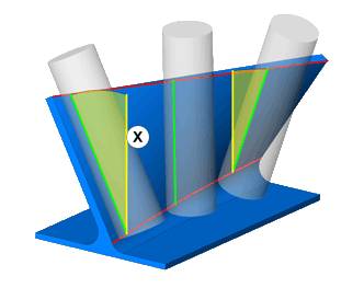
-
Automatic - select this option to have the system attempt to find a solution where the tool contacts the surface in a line. A Swarf surface must be selected. It is suggested to use the Outside, Inside, or Surface Normals option for the Machining Side parameter when using this option.
-
Shortest Distance - select this option to allow the system to define the tool orientation using the shortest distance between the upper and lower curves. This strategy is helpful when machining flat surfaces with sharp corners.
-
Fanning Distance - for use only with the Shortest Distance strategy, this is the distance from the intersection of two surfaces. Within this distance, the tool axis orientation begins to tilt. This helps to avoid sudden tool axis orientation changes.
The following example shows fanning with a value of zero. When the top of the tool reaches the corner it stops while the bottom of the tool continues to fan around the corner. This is a result of the upper and lower curve not having the same length. View Fanning Distance at Zero
The following example shows the fanning distance set to a larger value to cause the tool to more smoothly through the corner.View Large
Fanning Distance
-
-
Normal to guide curve - The tool axis is oriented normal to the guide curve.
- Sync with ISO curves - This parameter allows you to follow the ISO curves of the selected nurbs machining surface.
Extensions
The Extensions group provides the ability to extend the toolpath at the start and/or end of the toolpath in addition to any leads that are defined. You can also define a starting angle for the tool orientation at the beginning of the toolpath.
- Type - can be one of
three options:
- Automatic - Extends the front and rear of the rail curve tangentially by the specified distances. On a closed part, the extensions revolve along the toolpath.
- Align to Edges - The start and end of the toolpath are extended by the given distances. The tool axis is aligned to the edges of the surfaces.
- Start/End with angle - The tool axis is aligned to the edges and an additional angle is added to the initial tilting at the start, and the final tilting at the end of the surface edge.